


Main Characteristics
-
The main characteristics and their details are described below.
Each characteristic is specified at an ambient temperature of 25 degrees C and with the stipulated control voltage (± 1% or less error) applied. (Only the control voltage is specified for the temperature characteristics.)- 1) Rated output
Denotes the output when the rated current is input to the primary side. - 2) Residual output
Denotes the output when the primary side input is zero. This measurement is performed after the core is demagnetized (an AC current equivalent to the rated current is input to the primary side and slowly made zero). - 3) Linearity
Denotes the error in the actually measured output value and the estimate output voltage calculated by the least mean squares method from the output and residual output when the rated current and 1/2 rated current are input. - 4) Saturation current
Denotes the input current value for which the output deviates from the estimate output voltage by more than 10%. - 5) Linearity limits
Denotes the range of the input current value for which the output is within 1% of the estimate output voltage. - 6) Output temperature characteristic
Denotes the rate of temperature change of the output (value after the residual output is subtracted) when the rated current in input within the working temperature range. (The rate of change is shown per 1 degrees C with the output at 25 degrees C as the reference.) - 7) Residual output temperature characteristic
Denotes the temperature change of the residual output within the working temperature range. (The change per 1 degrees C is shown.) - 8) Response time
Denotes the output response time (ΔT) when a pulse current is input as the input current. ΔT is shown as the time difference of when the input and output waveforms drop to 80% of their initial levels.
However, set the smaller one on either input pulse current (di/dt)=100A/μs or If/μs. - 9) DC currents continuously flowing through board mount models (with a primary winding).
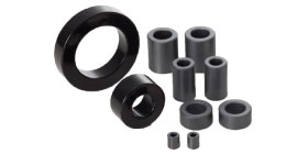
The DC currents continuously flowing through board mount models (with a primary winding) are limited by the wire diameter of the winding used in them. With some exceptions, our current sensors (with a primary winding) normally have 1/ 2 of the rated DC current set as a continuously flowing current. The relationships between the wire diameters of primary windings and the continuously flowing DC currents are summarized in the table below. Continuously flowing DC currents should be equal to the r.m.s. values of AC currents. - 10) Characteristics of core
-
- 11) Noise testing method
1. Effects of dv/dt
Waveform of the output voltage when the voltage pulse of dv/dt=300V/μs is applied.

2. Effects of impulse noise
Waveform of the output voltage when the impulse noise of rise time 1ns, pulse with 1μs, and voltage 2,000V is applied.


- 1) Rated output


