


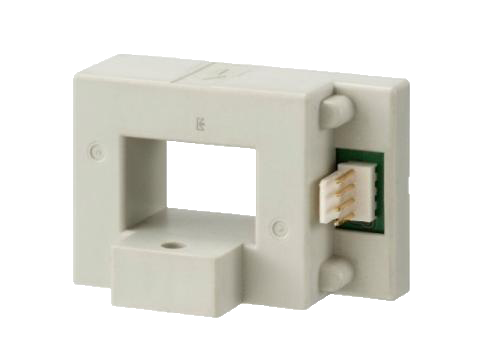
HC-TF Large current range / Bolt on type 
Dimensional outline drawing

![]()
Characteristics charts

![]()
Features
- Rated current: 50A–1600A
- Single-power supplies also available
Applications
Inverters, Servo drivers, Power supply equipment, Uninterruptible power supply (UPS), NC machine tools, Welders
Electrical characteristics Ta=25℃
| Type | HC-TF 050V4B15 |
HC-TF 100V4B15 |
HC-TF 400V4B15 |
HC-TF E10V4B15H |
HC-TF E16V4B15H |
|---|---|---|---|---|---|
| Rated current [If] | ±50A | ±100A | ±400A | ±1000A | ±1600A |
| Saturation current [Is] | ±150A | ±300A | ±1000A | ±2700A | ±2700A |
| Linearity limits | 0~±150A | 0~±300A | 0~±800A | 0~±2200A | 0~±2200A |
| Rated output [Vh] +If | V0+4V±1% (RL=10kΩ) | V0+4V±2% (RL=10kΩ) | |||
| Rated output [Vh] -If | V0-4V±1% (RL=10kΩ) | V0-4V±2% (RL=10kΩ) | |||
| Residual output [V0] | Within ±70mV | Within ±50mV | |||
| Output linearity | Within ±1% | ||||
| Response time | Within 10μs (The smaller one on either at di/dt = 100A/μs or If/μs.) | ||||
| Response performance | Within 10% | ||||
| Hysteresis voltage range | Within 30mV | ||||
| Output Temp. Coef. | Within ±0.1%/℃ | ||||
| Residual output Temp. Coef. | Within ±3mV/℃ | Within ±1.5mV/℃ | Within ±1mV/℃ | ||
| Control power supply | ±15V±5% | ||||
| Consumption current | Within 30mA | ||||
| Operating Temp. | -10℃~+80℃ | ||||
| Storage Temp. | -15℃~+85℃ | ||||
| Dielectric withstand voltage | 2500V AC 50/60Hz 1minute | ||||
| Insulation resistance | Not less than 500MΩ 500V DC | ||||
- Note1)
- The indicated residual voltage is the one after the core hysteresis is removed.
Consultations and Inquiries about Our Products
Current sensor user's guide
When using our current sensors, please read the following “Handling Precautions,” “Main Characteristics,” and “Product Labeling” and use them within the specified limits.
Click here for FAQs about current sensors