


It achieves high accuracy over a large bandwidth.
It has high sensitivity, high linearity and stable temperature characteristics.
The high frequency alternating current drive makes hysteresis very small.
This sensor has a small offset and enables high accuracy detection.
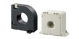
A flux gate current sensor has basically the same structure as a current sensor with a magnetic balance system, except that it has a magnetic probe coil instead of a Hall element.
The detectable current is within a range from 6 to 600A, and is perfect mainly for industrial equipment and medical equipment that require high accuracy measurement.
Fluxgate Current Sensor Series Lineup
-
HM Series
Operating Principle

This is a closed-loop type current sensor with a flux gate method that has secondary windings to lead the feedback current in order to offset the magnetic field by using the measured current.
A zero-flux detector is positioned close to the current bus, and the secondary winding (N turns) is wrapped around the core to offset the magnetic field created by the measured current (I). The zero-flux detector uses two winding cores connected to a square wave generator. In the feedback circuit, feedback current (I/N) is led through the secondary winding in order to keep the output of the zero-flux detector at zero at all times. By converting the feedback current to voltage by using a load resistance (RL), it becomes possible to obtain output relative to the measured current.Features
- It achieves high accuracy over a large bandwidth
- High linearity and stable temperature characteristics
- Resistant to external magnetic fields
- Very low noise output
Applications
- High precision power supply
- High precision inverter
- Medical equipment
- Test equipment
-
HF Series
Operating Principle

This is a closed-loop type current sensor with a flux gate method that has secondary windings to lead the feedback current in order to offset the magnetic field by using the measured current.
A magnetic probe coil instead of a Hall element is positioned on a part of the core so as to surround the current bus, and the secondary winding (N turns) is wrapped around the core to offset the magnetic field created by the input current (I).
In the feedback circuit, feedback current (I/N) is led through the secondary winding in order to keep the output of the magnetic probe coil at zero at all times. By converting the feedback current to voltage by using an internal load resistance (RL), it becomes possible to obtain output relative to the measured current.Features
- 5V single power supply and reference voltage (Vref) input/output is available
- Excellent temperature characteristics
- High speed response
- Over-current protection circuit
Applications
- Photovoltaic power system
- Fuel cell system
- High precision inverter
- Uninterruptible power supply
Search for other types of current sensors
Current Sensor Product Search
Search current sensor products by operating conditions.
Product information reference
Current Sensor User’s Guide
When using our current sensors, please read the following “Handling Precautions,” “Main Characteristics,” and “Product Labeling” and use them within the specified limits.
China RoHS Hazardous Substance Information
Click here for FAQs about current sensors